| During
1997 we developed a 64 channel amplifier system for MEG/MCG applications.
This work was done for Dr. Peter van Leeuwen at the EFMT
in Bochum where a BTI installation is used for MCG measurements. |
| We
were asked to develop an ECG amplifier system. The three main demands
for this application were : |
 |
No
digital circuitry may be used inside the shielded room in
order to prevent an increased noise level of the magnetic
sensors |
 |
Only
fiber optic connections between the front-end inside the room
and the equipment outside the room were allowed in order to
prevent the coupling of interference into the shielded room. |
 |
We
had to provide 64 analogue outputs in order to interface with
the 64 auxiliary inputs (with synchronized sigma delta 16-bit
ADCs) of the BTI signal processor hardware. |
| |
|
|
| |
| To
fulfill these demands a fully analog setup was chosen with a battery
powered front-end and an analog optical fiber signal link per channel.
The general configuration would be : |
 |
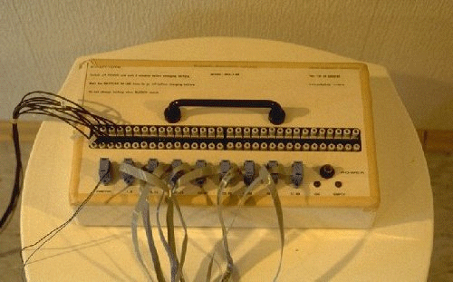
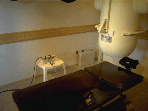
The
system has an isolated front-end inside the shielded room
and a receiver outside the room. |
 |
The
front-end contains up to 64 electrode amplifiers and is powered
by a 6V, 10Ah sealed lead-acid battery (approx. 8 hours continuous
operation). |
 |
The
amplified signals are transmitted to the receiver outside
the shielded room by plastic optical fibers (one optical fiber
per channel). |
 |
There
are no digital circuits in the front-end in order to prevent
interference to the MCG. |
 |
The
optical fiber links are the only connection between the front-end
and the receiver. The receiver is powered by the mains supply. |
|
| |
| The
receiver has up to 64 analog outputs on 37-pole D-type connectors.
The connection between the receiver and the Magnes is by unshielded
flatwires. The front-end is housed in a custom made plastic box
(no magnetic materials), the receiver is housed in a standard 19"
cabinet. A first prototype is currently under evaluation in Bochum
It was proved in a series of tests in Bochum that the amplifier
does not cause any significantly interference with the MCG signals.
FET input stages were used in order to insure minimal DC (< 10 pA)
and AC (<<1 pA) currents in the electrode wires. These small bias
currents did not cause significant interference to the MCG signals,
but nevertheless in the spectrum we could see that the magnetic
sensors were able to detect them. The bias currents are now the
main source of interference from the ECG amplifier to the MCG measurement;
the influence of the currents in the front-end box could be kept
below the level of the bias currents so long as the box so long
as the front-end was not placed too close to the Dewar (minimal
distance approx. 1 meter). Finally, a slow-start/stop power supply
circuit was incorporated to prevent current transients in the shielded
room (supply current is linearly increase/decreased during a 1 minute
time period). |


