HIGH QUALITY RECORDING OF BIOELECTRIC EVENTS. I: INTERFERENCE
REDUCTION, THEORY AND PRACTICE
A. C. MettingVanRijn, A. Peper, C. A. Grimbergen.
Academic Medical Center, Medical Physics Department, Meibergdreef
15 1105 AZ Amsterdam, The Netherlands.
- Keywords - Bioelectric recordings, Interference, Isolation, Driven right leg,
Guarding.
- Abstract - In the first part of this paper the various mechanisms that
could be the cause of interference in bioelectric recordings are reviewed. It is
demonstrated that the performance of a good amplifier can be seriously degraded if, for
its functioning, not the whole measurement situation is taken into account. Several
techniques to reduce interference, guarding and driven right leg circuits being the most
important, are analysed. In the second part of the paper some examples of the application
of the theory in practical situations are presented. The instrumentation amplifier circuit
normally used in bioelectric recordings is improved for measurements under difficult
circumstances. Another application is a low-cost 64 channel amplifier for multichannel ECG
recordings. The third application is a device that can be added to bioelectric measurement
systems and will provide a major reduction in interference.
I. INTRODUCTION
Bioelectric recordings are often disturbed by an excessive level of interference.
Although its origin in nearly all cases is clear -the mains power suplly - the cause of
the disturbance is not at all obvious because in many cases very sophisticated equipment
is used. Apparently, the use of equipment with very good specifications does not guarantee
interference free recordings. In this paper it is argued that if a significant reduction
of the level of intrference is persued, the whole measurement situation has to be
analised.
In most bioelectric measurements an interference level of 1 - 10 microV,p-p (less than 1%
of the peak-peak value of an ECG) is acceptable. As the noise of a typical electrode is
also several microV,p-p (Geddes and Baker, 1966a; Spekhorst et al., 1988), in most
circumstances 10 microV,p-p can be accepted as the upper level of interference.
The most common mechanisms of electrical mains interference are described in the following
paragraphs.
2. ORIGIN OF INTERFERENCE
2.1 Interference currents through the body
The capacitances between the patient, the power lines and ground cause a small
interference current to flow through the body (see Fig. 1). In the modeling of the
measurement situation the capacitance between the body and ground (Cbody) is
taken to be 300 pF and the capacitance between the body and the mains power (Cpow)
is taken to be 3 pF (Huhta and Webster, 1973; Forster, 1974) which values can be assumed
to be typical. These capacitances cause an interference current (i1 in Fig. 1)
of ca. 0.5 uA,p-p to flow from the power supply lines (220 V,rms, 50 Hz) through the body
to ground. It should be emphasized that Cpow and Cbody show large
variations and interference currents ten times as high as mentioned above are found
regularly. If an amplifier is connected to the patient, part of the current from mains to
patient (i1) will flow to ground through Zrl - the impedance of the
electrode-skin interface of the "neutral" electrode (the right leg electrode in
standard ECG measurements). Measurements without the use of a neutral electrode are
possible but are not treated here. The complications involved with these so called two
electrode measurements are extensively treated elsewhere (Thakor and Webster, 1980). The
portion of i1 that flows through Zrl causes a potential difference
between the average potential of the body and the amplifier common: the common mode
voltage (Vcm in Fig. 1).
2.2 Interference currents into the amplifier
In a model of an isolated bioelectric measurement (i. e. no galvanic connection between
the amplifier common and ground, switch open in Fig. 1.) the capacitances between the
amplifier common and mains (Csup) and between amplifier common and ground (Ciso)
should also be considered (see Fig. 1). Csup causes an additional interference
current (i2) to flow from the amplifier to ground, partially via Ciso
and partially via Zrl and Cbody. The portion of i2 that
flows through Zrl contributes to the common mode voltage.
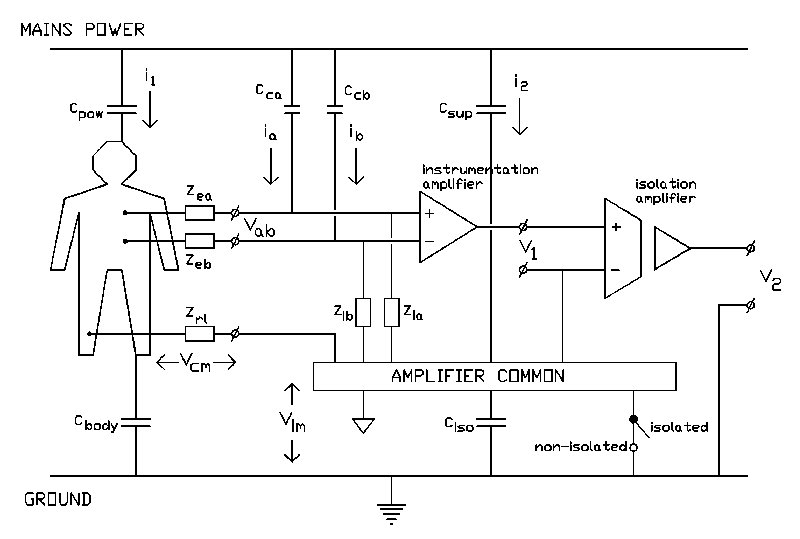
Fig.1 Block diagram of a bioelectric measurement. The capacitances between the
patient, the amplifier common and the measurement cables with respect to ground and mains
cause interference currents to flow: i1, i2,ia and ib.
In a non-isolated situation the amplifier common is connected to ground (switch closed).
The output voltage (V2) is registrated with respect to ground.
2.3 Interference currents into the measurement cables
A major source of interference in bioelectric measurements results from
the capacitive coupling of the measurement cables with the mains (Cca and Ccb
in Fig. 1). The currents induced in the wires (ia, ib in Fig. 1)
flow to the body via the electrodes and from the body to ground via Cbody and
via Zrl in series with Ciso. Because both the currents induced in
the wires and the electrode impedances generally differ significantly, a relatively large
differential voltage is produced between the amplifier inputs (Vab in Fig. 1).
The magnitude of this voltage is given by the following relation:
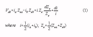
A typical situation with a mean current of 10 nA,p-p in the wires, a mean
electrode impedance of 20 kOhm and a relative difference in interference current and
electrode impedance of 50%, leads to an unacceptable high interference level of 200
microV,p-p.
2.4 Magnetically induced interference
Magnetically induced interference is easily distinguished from other types of
interference because it varies with the area and orientation of the loop formed by the
measurement cables. Suppression is easy in theory by reducing this area as much as
possible (twisting of cables) (Huhta and Webster, 1973). In practice, this is not always
feasible. For example: the usual electrode configuration in ECG measurements with
electrodes placed at the extremities of the body might causea considerable area between
the input cables. Shielding of the patient with a material with a high magnetic
permeability (mu-metal) is an impractical solution in most situations. Therefore it is
often necessary to lower the magnetic field itself by shielding the sources of magnetic
fields with multiple layers of mu-metal interleaved with heavy copper layers
(Motchenbacher and Fitchen, 1972) and/or by keeping all magnetic sources far from the
patient.
3. INTERFERENCE REDUCTION
3.1 Influence of common mode voltage
There are two ways by which a high common mode voltage may cause
interference. The first, obvious way is when the common mode rejection ratio of the
amplifier is limited. This mechanism is not often problematic with modern differential
amplifiers: a common mode rejection ratio of 80 - 90 dB is customary. A second, and much
more important way a high common mode voltage may cause interference is when there are
differences in electrode impedances and/or input impedances which convert common mode
voltage into a differential input voltage (see Fig. 1). This mechanism - often called
"the potential divider effect" (Huhta and Webster, 1973; Pacela, 1967) - is the
main reason why it is important to reduce the common mode voltage as much as possible. The
magnitude of the differential interference input-voltage generated this way, is given by
the following relation (see Fig. 1) :
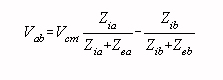
where Zia,b: input impedances
Zea,b: electrode impedances
It is instructive to rewrite this equation assuming the input impedances
to be much larger than the electrode impedances :
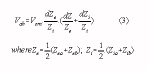
It appears that the level of interference generated by the potential divider effect
depends on the magnitude of the common mode voltage, the ratio of the average electrode
and input impedances, and on the relative differences in electrode and input impedances.
The usual electrodes may show a mean impedance of 20 kOhm at 50 Hz and impedance
differences of ca. 50 % (Almasi and Smitt, 1970; Grimnes, 1983; Geddes, 1972). Differences
in input impedances should not exist in a carefully designed amplifier system, but often
these differences are not easy to avoid. Differences in input impedances are often found
in multichannel measuring systems (an example is given in section 4.2.) but may also be
caused by the use of shielded input cables of different length.
3.2 Reduction of the common mode voltage
If the impedance differences of electrodes and inputs cannot be kept sufficiently low
to reduce the influence of the potential divider effect - the input impedances being as
high as possible - the only practical solution left is to reduce the actual common mode
voltage. There are three situations:
- The amplifier common is connected to ground (see Fig. 1, switch closed: no isolation):
The amount of interference current through Zrl is determined mainly by the
capacitance Cpow. Consequently, the common mode voltage is reduced if this
capacitance between body and mains is minimized.
- The amplifier common is not connected to ground (see Fig. 1 with switch open:
isolation): The resulting current through Zrl depends on the values of four
capacitances: Cpow, Cbody, Csup and Ciso. In
this situation, the common mode voltage might be reduced by minimizing the capacitance
between the amplifier common and mains (Csup) and the capacitance between the
amplifier common and ground (Ciso).
- In all cases, the common mode voltage can be largely reduced if a driven right leg
circuit is added (see Fig. 2). An extra amplifier drives the patient to the same voltage
as the voltage of the amplifier common. The voltage difference between patient and
amplifier common (= common mode voltage) can be made much smaller this way than the
voltage across Zrl in Fig. 2.
With the first method, rather low common mode voltages are possible if the impedance Zrl
is low (good electrode and extensive preparation of the skin) and the capacitance Cpow
is small (all power lines and mains powered devices far from the patient). In a typical
situation (Cpow = 3 pF, Zrl = 20 kOhm) the common mode
voltage is an acceptable 10 mV,p-p. In this case, a mean Zi = 20 MOhm, a mean Ze
= 20 kOhm and relative differences in Ze and Zi of 50 % results in
an interference voltage of 10 microV,p-p (see Eq.3). However, in clinical situations this
method is not used because the low impedance path that is formed between body and ground
brings the patient in a potentially unsafe situation (Olson, 1978).
An isolated measurement is very safe if the capacitance between the amplifier common and
ground (Ciso) and the capacitance between the amplifier common and mains (Csup
) are kept sufficiently small. However, the magnitude of the common mode voltage is only
then significantly lower than in the first situation, if Csup is much smaller
than Cpow and Ciso is much smaller than Cbody. Two
numerical examples will provide some clarification. Consider a good isolation amplifier
with a relatively small capacitance of the isolation barrier of 30 pF (Ciso =
30 pF). If the amplifier is small and battery powered the capacitance to the mains power
supply can be neglected (Csup < 1 pF). It can be calculated that under
typical conditions (Cbody = 300 pF, Cpow = 3 pF , Zrl =
20 kOhm), the common mode voltage will be small, approx. 1 mV,p-p.
A different situation is encountered with a multichannel measurement system in which
isolation is achieved with an isolated power supply. In this case Csup and Ciso
can be both as high as 100 pF and a large common mode voltage of approx. 200 mV,p-p would
be generated under typical conditions. Note that the leakage current does not exceed the
safety regulations (< 10 uA,rms), even if the patient touches ground or mains. An
example of a measurement system with relatively large capacitances to mains and ground is
given in section 4.2.
Isolated measurements can be problematic, even if the common mode voltage is kept small,
because the interference voltage across the isolation (isolation mode voltage, Vim in Fig.
1) is not rejected sufficiently (Pallas-Areny, 1988). Inspection of Fig. 1 shows that the
isolation mode voltage can be large in typical situations (for the two examples mentioned
above respectively 6 V,p-p and 120 V,p-p). Consequently, a very high isolation mode
rejection ratio (120 - 150 dB) is essential in an isolated bioelectric recording. A high
isolation mode rejection ratio can be achieved with modern photo-optically isolation
techniques (analog or digital) combined with a high gain front-end (thus reducing the
difference in magnitude between the amplified bioelectric signal that is transmitted
across the isolation barrier and the large isolation mode voltage).
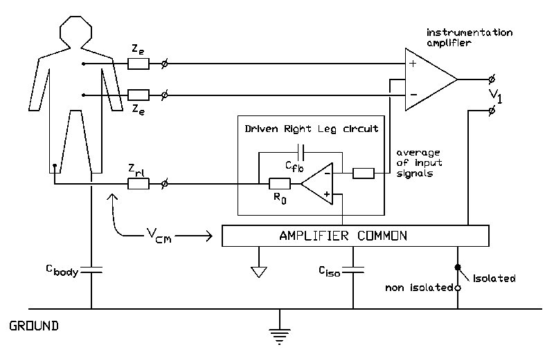
Fig.2 Driven right leg circuit. If the gain of the driven right leg circuit
is high, the common mode voltage (Vcm) is much smaller than the voltage across Zrl.
A proper driven right leg circuit (see Fig. 2) offers a large reduction of common mode
voltage magnitude in both isolated and non-isolated measurements by actively reducing the
voltage difference between patient and amplifier common; a reduction between 10 and 50 dB
is usually accomplished. A driven right leg circuit is the most practical way to reduce
the common mode voltage if a reduction of interference current through Zrl is not
feasible. In addition, the driven right leg circuit makes measurements reasonable safe in
a non-isolated situation (switch closed in Fig. 1 and Fig. 2) because a rather large
impedance between body and ground can be achieved by selecting a large resistor R0
(several MOhm) and a small feedback capacitor Cfb (< 1 nF). This feature can be used to
omit isolation amplifiers in experimental situations in which safety standards are not as
critical as in clinical situations. The main drawback of a driven right leg circuit is it
being potentially unstable (Winter and Webster, 1983). In practical designs, a compromise
between common mode suppression and possible instability - depending on circumstances -
must be found. This problem is worked out in more detail in the appendix.
3.3 Reduction of interference currents in the measurement cables
Given the inherent variability of the electrode impedances and the level of
interference among recordings (Eq. 1), there is only one practical way to reduce
interference currents in the wires: shielding of the measuring cables. The different
possible shielding techniques are treated in the following. 1) Shields connected to
amplifier common Simply connecting the shields to the amplifier eliminates
interference currents in the wires. However, it usually does not reduce the total level of
interference. The high capacitance of shielded input cables reduces the input impedance of
the amplifier resulting in an increase of the level of interference because of the
potential divider effect (Eq. 3). The common mode signal, which is the cause of this form
of interference, can not effectively be reduced with a driven right leg circuit because
the increased input capacitance of the amplifier easily results in instability of the
circuit (see appendix).
2) Guarding U When a shield is driven with the signal at the inner wire, there is
virtually no cable capacitance and its contribution to the input impedance of the circuit
is negligible (Morrison, 1977). This technique is usually known as guarding. A consequence
is that for each input an extra amplifier is needed to drive the shield.
3) Guarding with the average of the input signals If all shields are driven with
the average of the input signals (= common mode voltage), the input capacitance for common
mode signals is virtually small because there exists no potential difference between
shield and inner wire for these signals. Hence, there is no extra sensitivity to
interference signals caused by the potential divider effect. Stability problems of an
effective driven right leg circuit can be avoided with a careful design of the guarding
circuit (see appendix). This method is a good compromise between the other two shielding
techniques: good interference suppression is achieved with just one extra amplifier. A
drawback is that the input capacitance for differential signals is just as low as in the
situation with the shields connected to the amplifier common because for differential mode
signals the voltage difference between shield and inner core is not reduced by the
guarding circuit. The resultant low input impedance for differential mode signals at high
frequencies may lead to signal loss and distortion (Geddes and Baker, 1966b). However, in
normal ECG and EEG recordings which have a restricted frequency content (< 200 Hz), the
extra input capacitance for differential mode signals is not problematic if extremely long
measuring cables are avoided.
4. APPLICATIONS
4.1 An improved instrumentation amplifier
The 3-operational amplifier instrumentation amplifier shown in the inlay of Fig. 3 is
generally used as input stage in bioelectric measurements. Its input impedance is high and
a good common mode rejection ratio can be obtained without extensive trimming (Tobey et
al., 1971). Parameters as noise, bandwidth, input bias current and power consumption can
easily be controlled if the right operational amplifiers are chosen. A 3-operational
amplifier instrumentation amplifier was equipped with provisions for a driven right leg
and driven shields. The complete circuit is shown in Fig. 3. Some details will now be
discussed.
Guarding circuit Both shields are driven by the same buffer amplifier. This buffer
should have a gain of unity from DC up to a few MHz in order to assure stable operation of
the complete amplifier (see appendix). Some operational amplifiers used in a buffer
configuration have a gain larger than unity at high frequencies. Proper compensation
should be provided in these cases because of possible instability.
The input signal for the shield driver should be the average of the input signals. A good
approximation of this signal is the average of the inverting inputs. To compensate for the
capacitance of the inverting input of the input-operational amplifier, small capacitors (Cf)
with a value equal to the input capacitance must be added (see Fig. 3 and appendix). The
gain of the shield driver has been put to 0.99. This reduces the signal magnitude at the
shield to 99% of the average signal magnitude at the inner wires thereby improving the
stability of the guarding circuit and reducing the peaking in the frequency response,
while there remains a considerable reduction of the effective cable capacitance (a factor
100) (Morrison, 1977).
Driven right leg circuit The input signal for the driven right leg circuit should
be the average of the input signals (= common mode voltage). The output signal of the
shield drive buffer differs very little from this average signal for reasons described
above, and can be used for this purpose. The open loop gain of the driven right leg
circuit is 300 at 50 Hz resulting in a 50 dB increase in common mode rejection at this
frequency. This proved to be a good compromise between maximum common mode reduction and
stability requirements (see appendix).
For reasons of simplicity, the low frequency roll-off is not shown in the circuit of Fig.
3. In practical use the amplifier should have a low gain for DC signals to prevent
saturation caused by electrode off-set voltages to occur. There are several solutions for
DC suppression (Hamstra et al., 1984; McClellan, 1981).
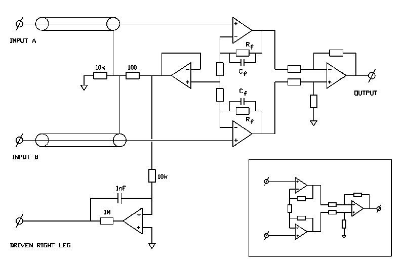
Fig.3 Biomedical instrumentation amplifier equipped with guarding and driven
right leg circuits, based on the three operational amplifier instrumentation amplifier
(see inlay).
4.2 A low-cost 64 channel ECG amplifier
In this paragraph, it will be demonstrated how an amplifier design can be improved to
acceptable standards without altering the complete layout. In the case taken as example -
a low cost 64 channel ECG amplifier for multichannel recording - there where good reasons,
most important being cost and size, to hold on to an amplifier set-up which was not
optimal in some respects.
The initial situation was:
- The input stage was formed by 64 separate instrumentation monolithic instrumentation
amplifiers which made the design compact and fairly cheap (Smit et al., 1987). - Each
instrumentation amplifier measured the potential difference between a chest electrode and
a reference signal. The reference signal was the average of the signals from the arms and
the left leg (Wilson Central Terminal), obtained by passive summation with three resistors
(300 kOhm). This led to a configuration in which the Wilson Central Terminal was connected
to 64 (inverting) amplifier inputs. - Isolation was necessary because of safety. However,
because 64 isolation amplifiers would make the system too expensive, isolation was
accomplished with a medical isolation transformer in the power supply.
These aspects presented some intrinsic interference problems. The interference
current flowing from the mains supply to the amplifier common (Csup
and Ciso. were in the order of 100 pF, see section 2.3 and 3.1) resulted
in a common mode signal of approx. 200 mV,p-p. The rejection of this large common
mode signal was poor because of the large differences in input impedances. The
input impedance of the reference lead was very low compared to the input impedance
of the 64 chest lead inputs because of the interconnection of 64 inverting inputs
and the low impedance of the Wilson Central Terminal. 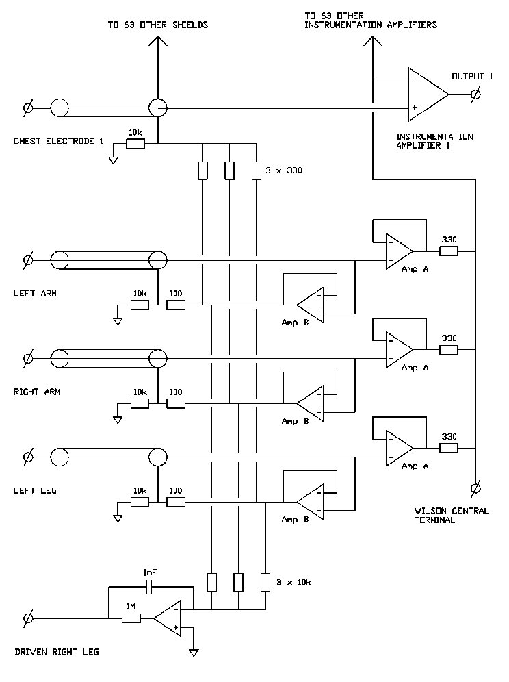
Fig.4 Reference (Wilson Central Terminal), guarding and driven right leg
circuits for a 64 channel ECG amplifier.
Good results were achieved with the extra input circuit shown in Fig. 4. The inclusion of
this circuit results in a system were all inputs have a very high impedance and the
impedance differences are small. All electrode leads are equipped with guarding. Two
buffers are used for the arm and left leg signals; an operational amplifier with a
superior noise figure is used for impedance transformation of the actual input signal (Amp
A) and another operational amplifier with a high input impedance, a high gain bandwidth
product and a stable high frequency performance is used as a shield driver (Amp B).
It should be emphasized that the performance of the complete 64 channel amplifier is
entirely determined by this input circuit. The equivalent input noise is primarily the
noise of the buffer amplifiers and the resultant common mode rejection ratio depends on
the driven right leg circuit gain, the input impedance of the buffer amplifiers and the
accuracy of the buffer amplifiers having unity gain. The specifications of the used
instrumentation amplifier, which are exceptionally good by any standard, have only a small
influence on the overall specifications. Several recording systems equipped with this 64
channel amplifier are now regularly in use in a Body Surface Mapping research project
(Reek et al., 1984).
4.3 An add-on device for a recording system
If the performance of a recording system is poor and the development of a complete
new amplifier system can not be considered, use can be made of the circuit shown
in Fig. 5. This circuit can be added to any amplifier. It suppresses common
mode voltage effectively and it provides guarding of the measurement cables
without deteriorating the performance of the existing amplifier. The extra input
capacitance and bias current can be neglected when high quality JFET operational
amplifiers are used. The circuit can be extended to any number of channels.
The device is in use for the recording of surface His-bundle potentials (Peper
et al., 1985) where very small signals (some microvolts) have to be recorded
and a low level of noise and interference is of utmost importance. 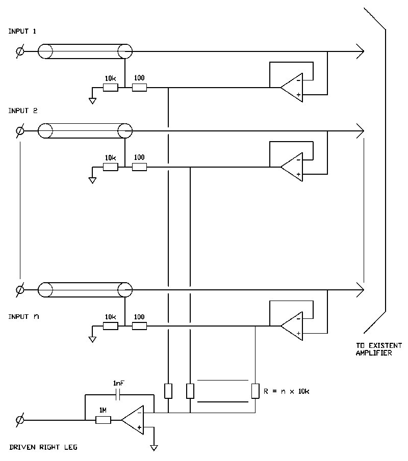
Fig.5 Add-on circuit for a n-channel bioelectric measurement. The circuit
reduces the common mode voltage (driven right leg circuit) and interference currents in
the measurement cables (guarding.
5. Discussion
In this paper it is demonstrated that considerable improvement can be obtained in the
susceptibility of amplifier systems for interference. Shielding combined with guarding
techniques to prevent interference currents in the measurement cables appeared to be of
utmost importance in this respect. Regrettably most of the commercially available
electrode systems do not provide standard shielded leads.
Common mode voltage reduction remains important because differences in electrode impedance
cause differential mode interference, even if the impedances of the amplifier inputs are
equal. Although good preparation of the electrodes and the skin may reduce this type of
interference, electrode impedances differ with every new recording and are inherently an
uncertain factor. Some reduction of the common mode voltage can be obtained by a good
isolation of the amplifier circuit, i.e. the capacitances of the amplifier to mains and
ground should be much smaller than the capacitances of the body to mains and ground.
However, these low capacitances are usually not easy to achieve and isolation must
therefore be regarded mainly as a way to improve patient safety. More effective common
mode voltage reduction can be obtained with a driven right leg circuit.
The combination of guarding and driven right leg circuits has been given special
attention. Both circuits form feedback loops and it is shown in the appendix that careful
dimensioning of each circuit is important to accomplish a stable combination. The
application presented in this study are designed to be stable even when the impedances in
the measurement situation (electrode impedances, body and amplifier capacitance etc.)
differ largely from the values encountered in a typical situation. Consequently, the
performance of these circuits can be improved in many measurement situations. A good
solution to this problem might be an optimalization of the guarding and driven right leg
circuits - dependent on the measurement situation - by an automated procedure with a
digital signal processing system. A special class of interference is the high frequency
interference caused by for instance fluorescent tubes or switching power supplies. Common
mode voltage reduction is less effective at higher frequencies as the driven right leg
circuit gain decreases with frequency. Moreover, at high frequencies the input impedance
of an amplifier will decrease because of its capacitive component, increasing the effect
of the common mode interference voltage. Although high frequencies are usually filtered
out in bioelectric measurements, amplifiers can easily saturate or produce low frequency
distortion components. High frequency interference therefore remains a factor of great
concern which in some situations may render high quality recordings impossible.
Acknowledgement
This research was supported by the Netherlands Foundation for Technical Research (STW).
References : Almasi, J. J., and Smitt, O. H. (1970) Systemic and random variations
of ECG electrode impedance.
Ann. N.Y.Acad.Sci.,170 (art.2),509.
Forster, I. C. (1974) Measurement of the body capacitance and a method of patientisolation
in mains environments. Med.Biol. Eng. & Comp., vol. september, 730.
Geddes, L. A. (1972) Electrodes and the measurements of bioelectric events. Wiley
Interscience, New York, 44.
Geddes, L. A., and Baker, L. E. (1966a) Chlorided silver electrodes. Med. Res. Eng., no.
6, 33.
Geddes, L. A. and Baker, L. E. (1966b) The relationship between input impedance and
electrode area in recording the ECG.Med.Biol.Eng.,vol.4,439.
Grimnes, S. (1983) Impedance measurements of individual skin surface electrodes. Med.
Biol.Eng. Comp., vol. 21, 750.
Hamstra G. H., Peper, A. and Grimbergen, C. A. (1984) Low-power, low-noise instrumentation
amplifier for physiological signals. Med. & Biol. Eng. & Comp., vol 22, 272.
Huhta, J. C., Webster, J. G. (1973) 60-Hz interference in electroardiography. IEEE
Tr.Biom.Eng., vol BME-20, no. 2, 91.
McClellan, A. D. (1981) Extracellular amplifier with bootstrapped input stage results in
high common-mode rejection", Med.Biol.Eng.Comp.,vol.19,657.
Morrison, R. (1977) Grounding and shielding techniques in instrumentation (second
edition). John Wiley & Sons, New York.
Motchenbacher, C. D. and Fitchen, F. C. (1972) Low-noise electronic design. John Wiley
& Sons, New York, 185.
Olson, W.H. (1978) Electrical safety, in "Medical instrumentation: application and
design" (editor: J. G. Webster). Houghton Mifflin Co. Boston, 667.
Pacela, A. F. (1967) Collecting the body's signals. Electronics, vol. 40,no. 14, 103.
Pallas-Areny, R. (1988) Interference-rejection characteristics of biopotential amplifiers:
a comperative analysis. IEEE Tr. Biom. Eng.,vol. BME-35, no. 11, 953.
Peper, A., Jonges, R., Losekoot, T. G. and Grimbergen, C. A. (1985) Recording of surface
His-Purkinje potentials", Med. Biol. Eng. Comp., vol 23, 365.
Reek E. J., Grimbergen, C. A. and van Oosterom, A. (1984) A low-cost 64 channel
microcomputer based data acquisition system for bedside registration of body surface maps.
Proc 11th Int. Congr. Electrocardiol., Caen, France, July 17.
Smit, H. W., Verton K. and Grimbergen, C. A. (1987) A low-cost multichannel preamplifier
for physiological signals. IEEE Tr. Biom. Eng., vol. BME-34, 307.
Spekhorst, H., SippensGroenewegen, A., David, G. K., Metting van Rijn, A. C., Broekhuysen,
P. (1988) Radiotransparent carbon fibre electrode for ECG recordings in the
catheterization laboratory. IEEE Tr. Biom. Eng., vol. BME-35, no. 5, 402.
Thakor, N.V., Webster, J.G. (1980) Ground-free ECG recording with two electrodes. IEEE Tr.
Biom. Eng., vol. BME-27, 699.
Tobey, G. E., Graeme, J. G. and Huelsman, L. P. (1971) Operational amplifiers: design and
applications. McGraw-Hill, 206.
Winter, B. B. and Webster, J. G. (1983) Driven-right-leg circuit design. IEEE
Trans. Biom.Eng., vol. BME-30, no. 1, 62.